8.1 KiB
audio-reactive-led-strip
Real-time LED strip music visualization using the ESP8266 and Python
Demo (click gif for video)

Overview
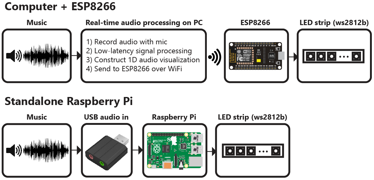
The repository includes everything needed to build an LED strip music visualizer (excluding hardware):
- Python real-time visualization code, which includes code for:
- Recording audio with a microphone (microphone.py)
- Digital signal processing (dsp.py)
- Constructing 1D visualizations (visualization.py)
- Sending pixel information to the ESP8266 over WiFi (led.py)
- Arduino firmware for the ESP8266 (ws2812_controller.ino)
What do I need to make one?
The following hardware is needed to build an LED strip music visualizer:
- Computer with Python 2.7 or 3.5 (Anaconda is recommended on Windows)
- Any ESP8266 module with RX1 pin exposed. ESP8266 modules can be purchased for as little as $5 to $10 USD. These modules are known to be compatible (but many others work too):
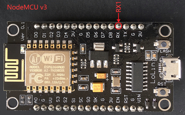
- NodeMCU v3
- Adafruit HUZZAH
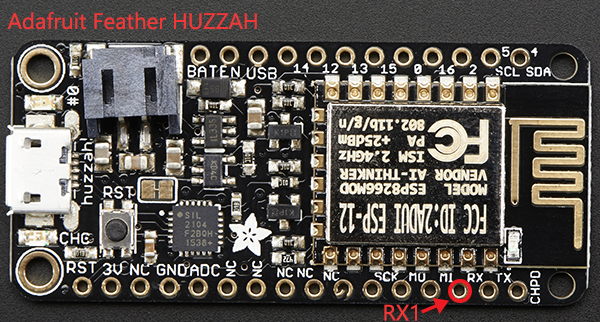
- Adafruit Feather HUZZAH
- Any ws2812b LED strip (such as Adafruit Neopixels). Many suppliers sell ws2812b LED strips for as little as $5-15 USD per meter.
Installation
Python Dependencies
Visualization code is compatible with Python 2.7 or 3.5. A few Python dependencies must also be installed:
- Numpy
- Scipy (for digital signal processing)
- PyQtGraph (for GUI visualization)
- PyAudio (for recording audio with microphone)
On Windows machines, the use of Anaconda is highly recommended. Anaconda simplifies the installation of Python dependencies, which is sometimes difficult on Windows.
Installing dependencies with Anaconda
Create a conda virtual environment (this step is optional but recommended)
conda create --name visualization-env python=3.5
activate visualization-env
Install dependencies using pip and the conda package manager
conda install numpy scipy pyqtgraph
pip install pyaudio
Installing dependencies without Anaconda
The pip package manager can also be used to install the python dependencies.
pip install numpy
pip install scipy
pip install pyqtgraph
pip install pyaudio
If pip is not found try using python -m pip install instead.
Arduino dependencies
ESP8266 firmare is uploaded using the Arduino IDE. See this tutorial to setup the Arduino IDE for ESP8266.
Hardware Connections
The ESP8266 has hardware support for I²S and this peripheral is used to control the ws2812b LED strip. This signficantly improves performance compared to bit-banging the IO pin. Unfortunately, this means that the LED strip must be connected to the RX1 pin, which is not accessible in some ESP8266 modules (such as the ESP-01).
The RX1 pin on the ESP8266 module should be connected to the data input pin of the ws2812b LED strip (often labelled DIN or D0).
For the NodeMCU v3 and Adafruit Feather HUZZAH, the location of the RX1 pin is shown in the images below. Many other modules also expose the RX1 pin.
Setup and Configuration
- Install Python and Python dependencies
- Install Arduino IDE and ESP8266 addon
- Download and extract all of the files in this repository onto your computer
- Connect the RX1 pin of your ESP8266 module to the data input pin of the ws2812b LED strip. Ensure that your LED strip is properly connected to a 5V power supply and that the ESP8266 and LED strip share a common electrical ground connection.
- In ws2812_controller.ino:
- Set
const char* ssidto your router's SSID - Set
const char* passwordto your router's password - Set
IPAddress gatewayto match your router's gateway - Set
IPAddress ipto the IP address that you would like your ESP8266 to use (your choice) - Set
#define NUM_LEDSto the number of LEDs in your LED strip
- Upload the ws2812_controller.ino firmware to the ESP8266. Ensure that you have selected the correct ESP8266 board from the boards menu. In the dropdown menu, set
CPU Frequencyto 160 MHz for optimal performance. - In config.py:
- Set
N_PIXELSto the number of LEDs in your LED strip (must matchNUM_LEDSin ws2812_controller.ino) - Set
UDP_IPto the IP address of your ESP8266 (must matchipin ws2812_controller.ino) - If needed, set
MIC_RATEto your microphone sampling rate in Hz. Most of the time you will not need to change this.
Installation for Raspberry Pi
Basic setup for headless operation
- Enable SSH by creating 'ssh' file in the boot directory of SD card
- Determine the pi's IP address by viewing router DHCP client list
- SSH into the pi using 'ssh pi@[pi-ip-here]' without the '[]'
- Change the password using the 'passwd' command
Installing the Python dependencies
Install python dependencies using apt-get
sudo apt-get update
sudo apt-get install python-numpy python-scipy python-pyaudio python-skimage
Install ws281x library
To install the ws281x library I recommend following this Adafruit tutorial.
sudo apt-get install build-essential python-dev git scons swig
git clone https://github.com/jgarff/rpi_ws281x.git
cd rpi_ws281x
scons
cd python
sudo python setup.py install
Audio device configuration
For the Raspberry Pi, a USB audio device needs to be configured as the default audio device.
Create/edit /etc/asound.conf
sudo nano /etc/asound.conf
Set the file to the following text
pcm.!default {
    type hw
    card 1
}
ctl.!default {
    type hw
    card 1
}
Next, set the USB device to as the default device by editing /usr/share/alsa/alsa.conf
sudo nano /usr/share/alsa/alsa.conf:
Change
defaults.ctl.card 0
defaults.pcm.card 0
To
defaults.ctl.card 1
defaults.pcm.card 1
Test the LED strip
- cd rpi_ws281x/python/examples
- sudo nano strandtest.py
- Configure the options at the top of the file. Enable logic inverting if you are using an inverting logic-level converter. Set the correct GPIO pin and number of pixels for the LED strip. You will likely need a logic-level converter to convert the Raspberry Pi's 3.3V logic to the 5V logic used by the ws2812b LED strip.
- Run example with 'sudo python strandtest.py'
Configure the visualization code
In config.py, set the device to 'pi' and configure the GPIO, LED and other hardware settings.
Running the Visualization
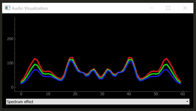
Once everything has been configured, run visualization.py to start the visualization. The visualization will automatically use your default recording device (microphone) as the audio input.
A PyQtGraph GUI will open to display the output of the visualization on the computer.
If you encounter any issues or have questions about this project, feel free to open a new issue.
Limitations
The visualization code currently supports up to 256 LEDs. Support for additional LEDs will be added in the near future.
License
All code in this project is released under the MIT License.